
Important: Read All Instructions Prior to Installation
Product Data
| Input Voltage | Output Voltage | Output Current | Size (LxWxH) |
| 100-240VAC | 100-240VAC | 1.8A max | 45.5 x 45 x 20.3 mm |
Compatible Load Types
| Load Symbol | Load type | Maximum Load | Remarks |
| Dimmable LED lamps | 200W @ 230V | Due to variety of LED lamp designs, maximum number LED lamps is further dependent on power factor result when connected to dimmer. | |
| Dimmable LED drivers | 200W @ 230V | Maximum permited number of drivers is 200W divided by driver nameplate power rating. | |
| Incandescent lighting, HV Halogen lamps | 400W @ 230V | ||
| Low voltage halogen lighting with eletronic transformers | 200W @ 230V |
ZigBee Clusters the device supports are as follows:
Input Clusters:
0x0000: Basic
0x0003: Identify
0x0004: Groups
0x0005: Scenes
0x0006: On/Off
0x0702: Simple Metering
0x0008: Level Control
0x0b04: Electrical Measurement
0x0b05: Diagnostics
Input Clusters:
0x0019: OTA
Function Introduction
- ZigBee AC phase cut dimmer based on latest ZigBee 3.0 protocol
- 100-240VAC Wide Input and Output Voltage
- Supports resistive loads or capacitive loads
- 1 Channel Output, Up to 400W
- Input and Output with Screw Terminals
- Enables to control ON/OFF and light intensity of connected light source
- ZigBee end device that supports Touchlink commissioning
- Can directly pair to a compatible ZigBee remote via Touchlink without a ZigBee Hub
- Supports self-forming ZigBee network without a ZigBee Hub and add other devices to the network
- Supports find and bind mode to bind with a ZigBee remote
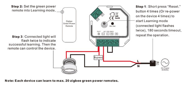
- Supports ZigBee green power and can bind up to 20 ZigBee green power remotes
- Compatible with universal ZigBee gateway products
- Mini Size, Easy to be Installed behind existing switches
- Radio Frequency : 2.4GHz (ZigBee)
Main Features
- Can operate under two-wire connection with no neutral wire or three-wire connection with neutral wire
- Advanced microprocessor control
- Implemented algorithm of smart light source detection
- Active power and energy metering functionality
- Soft start function
- Innovative minimum dimming level and startup brightness setting function
- Works with momentary switches, 2-3 way switching compatible
- To be installed behind existing switch plate, conforming to applicable regulations
The dimmer can operate the following loads:
- Conventional incandescent and HV halogen light sources
- MLV halogen lamps (with ferromagnetic transformers)
- ELV halogen lamps and dimmable LED bulbs (with electronic transformers)
- Dimmable LED bulbs
- Dimmable compact fluorescent CFL tube lamps
- Supported dimmable light sources (power factor > 0.5) with minimal power of 3VA using the Bypass (depending on the type of load)
Trailing edge setting to control the following types of loads:
- "Trailing edge" for resistive loads
- "Trailing edge" for capacitive loads
Safety & Warnings
- DO NOT install with mains power switched on
- DO NOT expose the device to moisture
- Must be installed by a licensed electrician in your state or territory
Operation
1. Connect according to the wiring diagram
2. This ZigBee device is a wireless receiver that communicates with a variety of ZigBee compatible systems This receiver receives and is controlled by wireless radio signals from the compatible ZigBee system
3. Zigbee Network Pairing through Coordinator or Hub
STEP 1: Remove the device from previous zigbee network if it has already been added to, otherwise pairing will fail. Please refer to the part "Factory Reset Manually".
STEP 2: From your ZigBee Controller or hub interface, choose to add lighting device and enter Pairing mode as instructed by the controller.

4. TouchLink to a Zigbee Remote

1) Directly TouchLink (both not added to a ZigBee network), each device can link with 1 remote.
4) After TouchLink, the device can be controlled by the linked remotes.
5. Removed from a Zigbee Network through Coordinator or Hub Interface

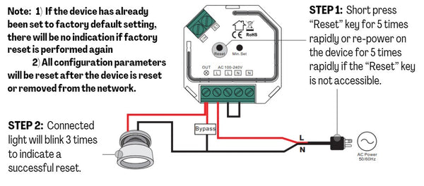
6. Factory Reset Manually
7. Factory Reset through a Zigbee Remote (Touch Reset)
Note: Make sure the device already added to a network, the remote added to the same one or not added to any network.

8. Find and Bind Mode
Note: Make sure the device and remote are already connected to the same Zigbee network.

9. Learning to a Zigbee Green Power Remote
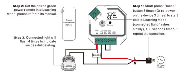
10. Delete Learning to a Zigbee Green Power Remote
11. Setup a Zigbee Network & Add Other Devices to the Network (No Coordinator Required)

STEP 2: Set another device or remote or touch panel into network pairing mode and pair to the network, refer to their manuals.
STEP 3: Pair more devices and remotes to the network, refer to their manuals.
STEP 4: Bind the added devices and remotes through Touchlink so that the devices can be controlled by the remotes, refer to their manuals.
Note:
1) Each added device can link and be controlled by up to 30 added remotes.
2) Each added remote can link and control up to 30 added devices.
12. OTA
The device supports firmware updating through OTA, and will acquire new firmware from zigbee controller or hub every 10 minutes automatically.
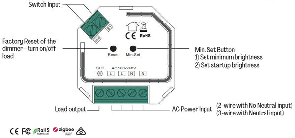
13. Minimum and Startup Brightness Setting Button
Set minimum brightness: Adjust brightness to a desired level, press and hold down the button for 3 seconds to set it as minimum brightness. The connected load will flash to confirm successful setting, then the dimming range is between this minimum brightness and 100%.
Delete minimum brightness: Adjust brightness to 100%, press and hold down the button for 3 seconds to delete the previously set minimum brightness, the connected load will flash to confirm successful deleting, then the dimming range is between 1% and 100%.
Set Startup Brightness: adjust the brightness of connected load to a desired level between 1%-50%, then double click “Min. set” key to set the brightness adjusted as startup brightness, then the load will go to the startup brightness when it is turned on, then drop down to the brightness it was the last time it was turned off.
Delete Startup Brightness: adjust the brightness of connected load to 0%, then double click “Min. set” key to delete the previously set startup brightness.
Note: startup brightness setting function is to avoid the phenomenon that some dimmable LED drivers can not be turned on after dimmed to a low level and turned off. Once setting a startup brightness, if the startup brightness is higher than the dimmed level before it was turned off, the driver will first go to the startup brightness when turned on then drop down to the dimmed level. If the startup brightness is lower than the dimmed level before turned off, the driver will directly go to the dimmed level after turned on.
14. Operation controlled by a momentary switch:
Once connected with a momentary switch, click once to switch ON/OFF, press and hold down it to increase/decrease light intensity.
Wiring Diagram
Notes for the diagrams:
L - terminal for live lead
N - terminal for neutral lead
Out - output terminal of the dimmer (controlling connected light source)
S1 - terminal for switch
COM - terminal for grounding to the switch connected to the dimmer
Supported external switch types:
1) Momentary push switch only.
Compatible load types and recommended values of power for supported loads:
| Supported Load Types | 100-240V~ | 100-240V~ | |
|
Resistive Loads Conventional incandescend and halogen light sources |
20-4000W @ 230V | 20-4000W @ 230V | |
|
Capacitative Loads Fluorescent tube lamp (compact/ with electronic ballast), electric transformer, LED |
Using Bypass: 3-200W @ 230V |
No Bypass Used: 20-200W @ 230V |
(1) 2-Wire Connection With No Neutral Wire

NOTE: The switch connected to the S1 terminal activates the basic functionality of the dimmer (turning the light on/off, dimming).
The Bypass is a device designed to work with the dimmers. It should be used when connecting LED bulbs or energy saving compact fluorescent lamps. The Bypass prevents flickering of the LED lights and the glowing of the turned off compact fluorescent lamps. In the case of 2-wire connection, the Bypass also allows to reduce minimum power of load required by the dimmer for correct operation. The Bypass provides powering of the dimmer in case of controlling the low loads of minimum power down to 3W (for cosφ>0.5).
(2) 3-Wire Connection With Neutral Lead

NOTE: Switch connected to the S1 terminal activates the basic functionality of the dimmer (turning the light on/off, dimming).
(3) Multiple Momentary or Push Switches Connection

The dimmer operates trailing edge dimming (reverse phase control). Please make sure the connected loads support trailing edge dimming. Please refer to the user manual of the lights or consult the supplier of the lights.
2 Way switching with toggle switch:


2 comments
Just how soon is this coming?
Apologies if this is the wrong place, but wanted clarification on if this can be used with a toggle switch? Is it possible to send mqtt message to the relay to set the switch type and turn it on remotely via a zigbee2mqtt setup?